Proximity Sensor via Ultrasonic Sonar Module: Difference between revisions
No edit summary |
No edit summary |
||
| Line 67: | Line 67: | ||
3. There are 5 pins of the US-100. From the back facing yourself, the 2 pins | 3. There are 5 pins of the US-100. From the back facing yourself, the 2 pins from the left are '''GROUND'''. The third pin from the left is the '''ECHO''', followed by the '''TRIGGER''' and lastly, the rightmost one, the '''VCC''' or the power. | ||
[[File:US100_BACK.jpg|200px]] [[File:US_100_FRONT.jpg|300px]] | [[File:US100_BACK.jpg|200px]] [[File:US_100_FRONT.jpg|300px]] | ||
Revision as of 09:17, 23 April 2014
Part of the Sensors and Controls Project, this Arduino micro-based Proximity Sensor integrates of an Ultrasonic Sonar module. With this, one can easily monitor if there's someone near or around a specific area, say, room, door, gate.
I. OBJECTIVES
- To make an Arduino based Proximity sensor via Ultrasonic Sonar module
- To simulate effectiveness by varying distances
II. MATERIALS & COMPONENTS
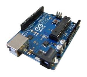
- Arduino micro/ Arduino UNO
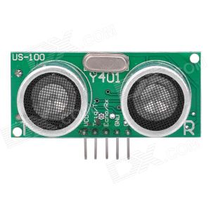
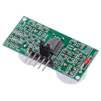
- Ultrasonic Sonar Module (US-100)
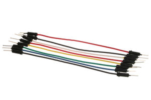
- Jumper wires
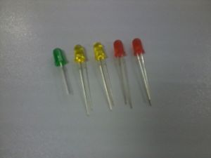
- 5 (Light Emitting Diodes) LEDs
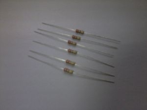
- 6 330K ohms Resistors
- Piezo Buzzer
- Computer (with Arduino 1.0.5 Software)
III. PROCEDURES
1. Prepare all the materials.
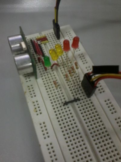
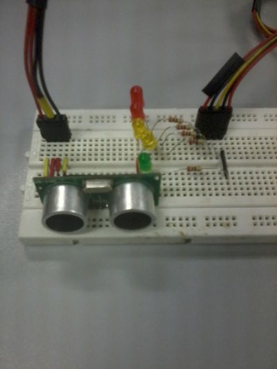
2. Put the corresponding components onto the breadboard. Make sure that the pins of the components are properly put to ensure the efficiency of the circuit.
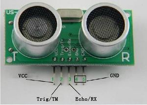
3. There are 5 pins of the US-100. From the back facing yourself, the 2 pins from the left are GROUND. The third pin from the left is the ECHO, followed by the TRIGGER and lastly, the rightmost one, the VCC or the power.
4. Connect the TRIGGER pin to Pin 6 of the Arduino. Connect the ECHO pin to Pin 7 of the Arduino. Make a connection between the 2 GROUND pins and connect it to GROUND pin of the Arduino. Also connect the VCC or power to the 5V pin of the Arduino.
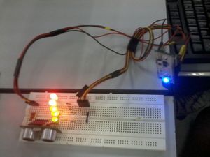
5. For the indication purposes, you will connect 3 LEDs and a small buzzer. The GROUND pins of the LEDs and piezo buzzer will be connected to the GROUND pin of the US-100. The ANODE pins of LED1 to pin 8, LED2 to pin 9, LED3 to pin 10, LED4 to pin11 and LED5 to pin12.
6. Have the code for the given circuit, use the Arduino 1.0.5 to program the operation of the circuit. See the code below and just copy and paste it on the Arduino 1.0.5.
7. Verify the code that you program. As it was verified, upload the code to the arduino and you can now test the capabilities of the proximity sensor.
IV. SIMULATION
As soon as you upload the code on the arduino, it will take seconds for the sensor to be working efficiently.
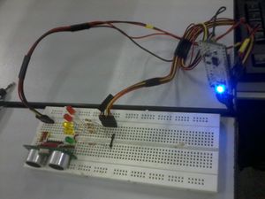
- When something is greater than 3 meter range, the LEDs will not light up.
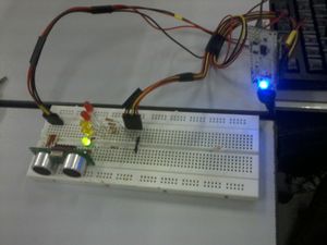
- When something is within the range of 2.51 to 3 meters, the GREEN light will turn on.
- When something is within the range of 2.1 to 2.5 meters, the GREEN light and one YELLOW light will light up.
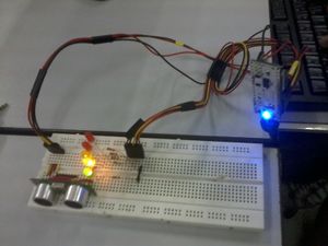
- When something is within the range of 1.51 to 2 meters, the GREEN light, and the 2 YELLOW lights will light up.
- When something is within the range of 1.1 to 1.5 meters, the GREEN light, the 2 YELLOW lights and one RED light will light up.
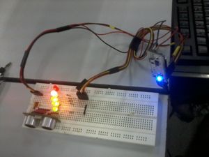
- When something is very near and within the range of 0 to 1 meter, ALL LEDs will light up.
V. OTHER PHOTOS

