UP-FM Transmitter: Difference between revisions
No edit summary |
|||
| Line 75: | Line 75: | ||
'''A. Making a Simple Antenna:''' | '''A. Making a Simple Antenna:''' | ||
*Since you don't have an ideal antenna,you will use a solid wire (no.22,) as a substitute antenna.Cut a solid wire about 32 cm(centimeters) and stripe one end at least 1 cm. Also cut the GPIO cable wire near the socket and leave at least 1 cm wire on it.Stripe the wire near the GPIO socket. Combine both ends of the solid wire and GPIO socket using lead and soldering iron. | *Since you don't have an ideal antenna,you will use a solid wire (no.22,) as a substitute antenna.Cut a solid wire about 32 cm(centimeters) and stripe one end at least 1 cm. Also cut the GPIO cable wire near the socket and leave at least 1 cm wire on it.Stripe the wire near the GPIO socket. Combine both ends of the solid wire and GPIO socket using lead and soldering iron as shown below.Wrap the soldered wire ang GPIO with the tape so that it will not stumble. | ||
Revision as of 12:04, 23 April 2014
DESCRIPTION
Raspberry PI-based FM transmitter programmed to transmit FM signals streamed in the the UP-FM website using SOX(Sound exchange) application.
SPECS
- Input stream via ethernet: up-fm.org
- Low-power FM transmission: analog at 87.MHz
- Can amplify the FM signal(output) of the transmitter for covering longer distance.
I. COMPONENTS
a. For the PIfm:
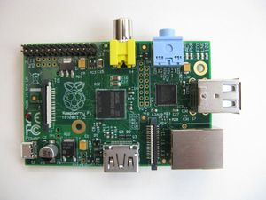
- Raspberry Pi (model B)
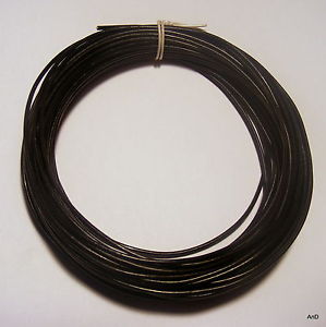
- Solid wire (no. 22)
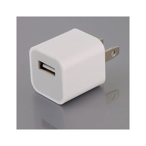
- 5 Volts,2 Amp. Power Brick
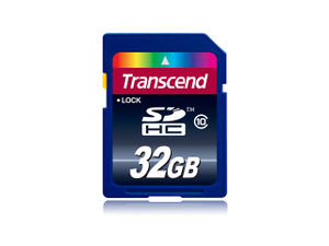
- SD card(at least 4 GB) with Raspbian "wheezy" O.S. on it
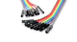
- GPIO wire
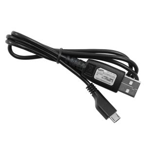
- USB micro
b.For programming:
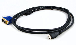
- VGG to HDMI cable
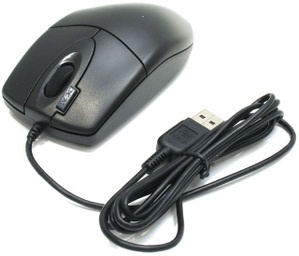
- USB mouse
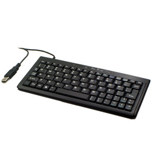
- USB keyboard
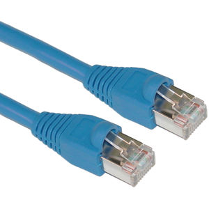
- Ethernet cable(for internet connection)
- monitor
PROCEEDURES
A. Making a Simple Antenna:
- Since you don't have an ideal antenna,you will use a solid wire (no.22,) as a substitute antenna.Cut a solid wire about 32 cm(centimeters) and stripe one end at least 1 cm. Also cut the GPIO cable wire near the socket and leave at least 1 cm wire on it.Stripe the wire near the GPIO socket. Combine both ends of the solid wire and GPIO socket using lead and soldering iron as shown below.Wrap the soldered wire ang GPIO with the tape so that it will not stumble.

